Monday, December 2, 2013

Ten-minute hack: Bringing sanity to your spare wires

Over the years, I've accumulated a lot of spare wire of various forms and flavors. And over the years, I've tried a couple of ways of managing this mess of wire, including a big "Strand Century" lightbox I scrounged in college and a shelf where things were haphazardly tossed. But after an organization-catastrophe-induced creative spit-balling session with my significant other on the issue, I think I have the solution to beat all solutions.
HANG ALL THE CABLES!

Preparation

This is a two-ingredient hack.
  1. Wire shelving. You probably have some somewhere in the place you store your wire.
  2. Lots and lots of self-gripping cable ties (1 per wire). These are easily the most oft-used hacking tool in my toolbelt; when you need some stuff fastened right now, they're the go-to gadget. Cheap, too.

Ten-minute hack

For each wire:


  1. Loop the end of the wire with the self-gripping cable tie.
  2. Coil the wire and tie it off with the rest of the tie, leaving a few inches of "tail" unstuck.
  3. Press the cable tie into the wire shelving from below, loop the loose end of the cable tie over one of the shelving wires, and stick it back down to the rest of the velcro.

Final thoughts

The result is straightforward and easy to work with.
All my wires, just hangin' out.

Pros

  1. The wires pop back off the shelf with a little bit of side-pressure; press so the shelving wire separates the end of the cable tie, and off it goes.
  2. With the wires hung in this way, it's much easier to see which is which than with a flat storage solution.

Cons

The only one I can think of is that some cables will of course exceed the weight limit of the velcro (if you have any that exceed the weight limit of your shelving wires, I'd like to know what you're up to!).


Monday, November 25, 2013

Building a Microscope

Recently, I stumbled across some directions for making my own microscope with a small collection of hardware-store parts and a smartphone. It looked like fun, so I thought I'd give it a try!


Overall, I'd say this project turned out pretty well. The directions on Instructables were very straight-forward. The only part I had to wing a bit was drilling the hole for the lens; I ended up using a 1/4" bit and "wiggling" a bit to enlarge the hole. Even still, the lens was a very tight fit, and it didn't fit quite flat. But it seems to have fit flat enough to give me good images.

One issue I encountered with the final construct was that I couldn't get the stage as close to the lens as it wanted to be to make focusing easy. I removed some washers, but still had issue. The easiest solution turned out to be simply stacking two blank slides underneath my subject matter.


Of course, once I got the thing assembled, it was time to try it out! :) I found a pretty inexpensive set of sample slides from Elenco and gave them a look!


My favorite thing about this rig is that the smartphone camera is so straightforward to operate; electronic zoom, auto focus. And of course, capturing images with the built-in camera couldn't be more straightforward!

Microfilm reference slides

Bird feather
Nylon fiber
Grasshopper wing
Grasshopper leg
GENTLEMEN, BEHOLD! CORN(starch)!
Fish scale
I tried adding an LED touch-light as under-lighting for the stage, but it blew out the camera; this might work if I used some semi-translucent material to block the intensity.


Wednesday, November 20, 2013

Experience building the RadioShack 3D LED Cube Kit

While looking for something to use a gift card on, I stumbled across the Radio Shack 3D LED Cube Kit for Arduino. It'd been awhile since I'd tried building an electronics board project from scratch, and I'd seen some clever demos of "3D pixel" displays; I thought I'd try my hand at putting this together. What follows is my experience with it.


Sunday, November 3, 2013

Personal experience: Patching a Galaxy Nexus with (expired) sugru


After several lucky years, I finally dropped my Galaxy Nexus in just the right way to crack a corner of the screen. I did a bit of research and found that one of the things sugru can be used for is to shore up a crack like that. I gave it a try, and I'm pretty happy with the results. The full steps are here; this is my personal experience following this process.

Note: If you follow this hack, be aware that it is not suitable for repairing cracks that intrude into the display or touch-sensitive areas of the screen. The hack guide on sugru.com points that out also, but I wanted to make it clear here to save you the trip if you've got a bigger crack.

So, some thoughts:

  1. Sugru is great stuff to work with. It's easy to mould, cleans quickly off of hands, and cures to a very nice, smooth-but-grippy surface. Documentation on it warns of possible allergic reactions to uncured sugru; I had no problems.
  2. The package of sugru I used was a free gift from a project last year; it was actually significantly past the expiration date (2012-12-13). I found that it still worked, but subsequent comments should factor that in.
  3. I found the steps of the guide suggesting you "delicately place the sugru into cracks" and "gently guide your finger" to be pretty untenable; the sugru I was working with had the texture of Play-Doh and tended to rub off of the phone or break up with too much handling. As a result, I ended up with a bit of a bulge in the finished product; I find it passable, but my wife doesn't score it to highly for attractiveness and it fires both of our OCD circuits. :) There is a good FAQ on how to get a smooth finish; I didn't try this process myself. I had thought that perhaps kneading it would make it less gummy, but I didn't try that; the same FAQ suggests this would not be desirable.
  4. My biggest concern trying this was that I'd inadvertently cover the front-facing camera. Fortunately, keeping the sugru off of the camera was quite easy, and I've noticed no diminished picture quality.
Sugru's pretty handy stuff. Now that I've gotten a chance to try it, I'm going to add it to my toolbox on future projects.

Thursday, September 26, 2013

Frances's Tracing Game v1.04: On Coordinate Transforms

As one bug dies, another is born. So it goes, so it goes. :)

As  I prepared to publish version 1.03 of Frances's Tracing Game, I took a glance at the statistics and suggestions from the Google Play Store and noticed that many newer Androids couldn't pick up the latest build because I had the minimum SDK version set to 1. I forked the project (Play Store lets you publish multiple binaries under the same app depending on the version of the client's phone), then in the fork I bumped the minimum up to SDK 4 and targeted SDK 11.

That introduced a new oddity: Apparently, my game had been running in a compatibility mode this entire time (due to its claim that it targeted SDK 1); as a result, the screen had been scaled automatically to fit the ancient Android form factor seen in the days of the Nexus 1. When I bumped to SDK4, the compatibility mode went away and my shapes were suddenly far too small to be traced by even clever fingers (screen resolution has improved a lot since the Nexus One days). The Android screen format rules have an awful lot of complexity to them, but to make a long story short: it is best to assume that your client's device could fit just about any rectangular form factor, much like we do with desktop PC programming.

Fortunately, this is an old problem with some old solutions. Many graphics libraries (such as OpenGL) provide a layer of transformations to make it easy to convert from one coordinate space to another. Android's graphics SDK is no exception; the Canvas object supports scaling and translation methods to tweak the underlying matrix that maps pixels in the canvas to pixels on the screen. I'd already used translation previously to center the image; now I just need to use scaling to balloon the image to fit the width of the screen.

Here's the basics of the tweaks I made; if you want to see the full code, it's hosted on GitHub.

Step 1: Tweak the scale

Tweaking the scale is extremely straightforward in Android; there's a pair of scale() methods that wrap the matrix multiplication logic for convenience (note: if you haven't done graphics programming, matrix algebra is basically the bread and butter of shifting coordinate spaces; Wikipedia can get you started on the concepts). I'm using this method, which includes the concept of a pivot point (the point around which the scaling should occur) to scale from the center of my image.

The only interesting part is determining how much to scale. I want to take up about 80% of the space, so I'm solving for S in the equations
final_image_width = 80% * screen_width
final_image_width = S * initial_image_width

This resolves to S = 80% * screen_width / initial_image_width, which I store and use as the scaling factor to rescale the canvas. Since the canvas itself is scaled, the image, line thickness I use for drawing, and pink tracing overlays are all correctly rendered without having to change the rest of the drawing logic.

Step 2: Unscale the touch

The only remaining issue is that the touch events we receive don't go through the rendering logic to be scaled. So for touch events we get from the screen, we need to reverse the scaling operation to get them back into the image coordinate space to determine if they were close to one of the tracing lines. I could have done this by grabbing the canvas's matrix with getMatrix() and inverting it (for a given transformation matrix, inverting the matrix gives you the reverse transformation). But I got a little bit fancy instead; the steps to reverse the scaling of the point (factoring in the pivot) are basically as follows:
  1. subtract the pivot coordinates from the point coordinates (this would translate a point on the pivot to (0,0), which is what you want because that point doesn't move under scaling).
  2. Multiply the point coordinates by 1/scale_factor.
  3. Add the pivot coordinates back to the point coordinates (reversing the translation).
It's mathematically simple enough that I think it's clearer to just represent it directly without the matrix (though just using the matrix inverse might very well have been less code!).

The Result


Image from the game: A smiling face, with the word "Smile" beneath it.
I am not unhappy. :)

I'm pretty happy with the result. Frances's game looks good on a 7-inch tablet and on a smartphone. I also added a text label for each picture, because she's getting older and is starting to read and write. I passed the labels through the canvas transformation, which leads to some odd scaling that's dependent upon the underlying size of the traced image; I might make some time to clean that up later. 

Feel free to download it to your own device if you'd like; it's free and will never include ads (because what possible use could ads be in a toddler's tracing game other than to junk-up the advertiser's signal with unintended clicks?).

I have no idea if this simple game will hold her interest much longer; it may soon be time to make her something new. And there's still the question of what to make for Cecilia, but there's a bit of time there; she's not very interested in tablets right now because she just realized that when she kicks her legs, her bounce-chair moves. I have to admit, that's pretty cool.

Thursday, September 19, 2013

Let's Tear Up: LM465 x10 Lamplinc module

I have a spare x10 module that is starting to get flaky, and I find myself using the basic non-INSTEON x10s less and less. So, I thought it might be fun to pop it open and see what's inside.


Disclaimer: We're dealing with a 110v AC device with some decently-sized capacitors. If you choose to do something this silly in the privacy of your own home, do be careful, and maybe probably don't plug it into the wall with the case off or anything ridiculous like that.


Friday, September 13, 2013

Reflections on Home Automation

It's been a little while since I've put more time into my home automation program. I've been feeling a little slowed down by the hardware available to me. My current solution for automation is an INSTEON network---a few wall switches and X10 relays with a central controller, itself driven by Belphanior. Recently, the communication between the controller and the wall switches seems to have gone out, and diagnosing the issue has been difficult.

Having worked with INSTEON for awhile now, I know a couple of features I'd be looking for in the next iteration of the hardware I used:

Diagnostic Tools: The biggest challenge with working with INSTEON is that when two devices cannot see each other, the root cause can be hard to determine. Ideally, I'd like to have a way to monitor the airwaves for the INSTEON signal to verify it is being transmitted and received correctly, but I'm unaware of any dedicated diagnostic monitoring devices for this purpose.

Status Feedback: While in principle INSTEON includes status updates to and from the devices, in practice I've found it to be spotty and not sufficiently reliable to base any sense of the house's state upon.

Security: INSTEON is protected by a longer ID than X10, but there's nothing really to prevent someone equipped with the right technology from radio-signalling the controllers, listening for their addresses in the radio chatter, etc. While I'm sure I can rely on security through obscurity in the short run, it's probably wise to lock down the signals longer-term.

I'll have to do some research; I'm not sure what other devices are available on the market to satisfy these goals (especially ones that might fit into a wall-socket form factor).

Monday, May 27, 2013

Frances's Tracing Game v1.03

I love three-day weekends. They give you time to think!

I've dusted off Frances's tracing game and finally fixed a niggling bug that had been bothering me. I'd taken a shortcut on centering the images on the screen by putting the image in a view that was embedded within a larger view. That solution had been playing passably, but it had annoying side-effects in Jellybean:
  1. Touch-drags that started outside the image didn't register when you dragged inward.
  2. As the drag operation happened, an annoying grey rectangle would flicker around the frame of the inner view. I never figued out the root cause of that.
I therefore ditched the two-view solution and did the math internally to set up the images in the center of the view (there's a convenient Canvas.translate method to do the offsetting for me in terms of drawing, and I do the translation of touch events from view coordinates to image coordinates myself).

There's a lesson in this. Sometimes, an operating system changes and it becomes clear that the OS's developers don't have your use case in mind. When that happens, there are a couple of ways you can respond. But when you're working on a hobby project and don't have the clout to steer the OS project itself, it's often easier to adapt to the changes than it is to push back. Don't be afraid to replace someone else's functionality with your own code. But when you can contribute, do; the svg-android renderer instance that I use seems to have issue with some flavors of transform logic, and if I don't find that this has been fixed in later versions, I plan to patch it and submit the changes back to the maintainers.

The new version of Frances's Tracing Game should be available in the app store some time today.

On a related note, there's one more bug to fix... I'm going to have to figure out what to do about the title. Frances herself is growing out of this game, but her younger sister was born this week. Welcome to the world, Cecilia!

Tuesday, May 14, 2013

Return of the Arduino part 3: mount the transmitter LED and load in the control code.

With the IR sensor and the status indicator LEDs in place, the only remaining steps are to wire up the IR transmitter and load the control software. Relative to everything else, this is the easy part. :)

My IR LED of choice is a 940nm LED that I picked up from Radio Shack. I used a basically direct connection to one of the digital output ports on the Arduino. The only complexity of this part is  the desire to make the IR trasmitter pretty mobile; I need to be able to position the receiver and transmitter separately from each other so I don't need to put a table in front of the TV to hold the enclosure. Since the LED is external to the enclosure and positionable, I grabbed some male-female servo extension cables from Amazon. I snipped one in half and glued the male end to the enclosure, making an external-facing plug.

Plug glued in position on the enclosure.

I then did away with the white wire (leaving only two channels) and soldered the black wire to the common ground used by the LEDs (the red wire gets a breadboard jumper wire and connected to digital port 13.

The LED side of the wiring is simpler. Cutting the male plug off of another servo extender and stripping out its white wire, I soldered the IR LED onto the remaining wires and added a bit of shrink tubing to clean everything up.

IR LED ready to be installed. Two leads off of it and some shrink-tubing to hold it all in place.

The final software package is available on Github. It's readily configurable for details, but its default configuration is as follows:

  • Listen for a signal from my remote (I happen to have a spare "blue button" that works just great).
  • When the signal is recognized, blink twice and begin a half-hour countdown.
  • At end of countdown, fire the off signal and go back to listenening for input.
 I ran a test (with the timer temporarily overridden from a half-hour to five seconds), and I'm pretty happy with the results!


Overall, this has been a pretty educational project. In the future, I'll try and add the Ethernet shield so that I can wire computer control into the entertainment system.

Monday, May 6, 2013

Return of the Arduino part 2: status indicators are your friends

The essence of user-friendliness is feedback. I won't be rivaling Apple with my little creation, but having more than zero indication that the IR receiver is actually picking up signal is probably wise. So the next step in the project was to mount some LEDs to the case to give me a bit of status indication.

A quick trip to Radio Shack netted me three red LEDs (2.6v, 28mA, 10mcd), one green LED (2.1v, 25mA, 6.3mcd), and a quad of 220-ohm resistors (and some 1K-ohm resistors). One thing I've learned during this process is to verify everything before busting out the permanent-connection hardware; before soldering or gluing anything, I bread-boarded the LEDs and used a slight modification on the Arduino "Fading" demo to confirm that all four LEDs would light. This turned out to be wise; my initial plan had been to use a 1K-ohm resistor between all four cathodes (in parallel) and ground, but I discovered that allowed too much back-current to leak across the LEDs---not desirable at all.

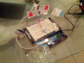
Breadboard. Arduino is connected by wires to four 220-ohm resistors, each leading to an LED, all leading to ground.
Final configuration for the LEDs and resistors on the testing breadboard.

Once I'd verified the configuration, it was time to get to work. Trimming the anode leads a bit on the LEDs, I soldered one resistor to each anode. I then grabbed my Dewalt and 3/16" bit again and bored four parallel holes in the upper half of the case, then glued the LEDs in place. Due to a slight mix-up on my part, the green LED ended up with its resistor on the cathode, but no harm seemed to be done. I soldered all the cathode leads (including the resistor lead from the green LED) into one, and left the anode leads to be connected to the Arduino.

I ran into a bit of a conundrum at this point: with the LEDs living on the top shell, I wanted some flexible wire with some nice, solid end plugs to connect the LEDs to the Arduino control pins, but nothing in my kit really fit the description. Fortunately, I discovered that Radio Shack sells a SideKick basic kit that includes what the kit calls "breadboard jumper wire." It turned out to be the perfect tool for the job if I cut them in half and soldered the loose wire to my LED leads.

With the jumper wires in place, I connected the LED anodes to Arduino pins 6, 9, 10, and 11, and the cathodes to one of the two GND pins. I then wrote a couple of short LED test functions:
// LED control library, by Mark T. Tomczak
// Public domain
// To use:
// * Call SetupLedControl with an array of LED inputs IDs
//   (-1 terminates the array as a sentinel value)
// * Call functions in the library to control the LEDs.

// Control LED firing patterns
// -1 used as sentinel value
int *g_led_control_leds;
int g_led_control_num_leds = 0;

// *leds is the arraay of LED pin IDs, terminated with a sentinel value of -1.
void SetupLedControl(int *leds) {
  g_led_control_leds = leds;
  g_led_control_num_leds = 0;
  while(*leds != -1) {
    g_led_control_num_leds++;
    pinMode(*leds, OUTPUT);
    leds++;     
  }
}

// Blink several times (off-on-off).
// - times: number of times to blink
// - flash_delay_millis: Number of milliseconds to wait
//   before toggling the light on or off. void FlashLights(int times, int flash_delay_millis) {
  for(int i=0; i < times; i++) {
    for(int i=0; i < g_led_control_num_leds; i++) {
      analogWrite(g_led_control_leds[i], 255);
    }
    delay(flash_delay_millis);
    for(int i=0; i < g_led_control_num_leds; i++) {
      analogWrite(g_led_control_leds[i], 0);
    }
    delay(flash_delay_millis);   
  }
}

// This is a fun little function that delays a specified
// number of milliseconds, while showing the time remaining as the
// intensity of several LEDs.
// 
// When all the time is remaining, the LEDs all glow at maximum brightness.
// Elapsing time is shown as the LEDs slowly going out one-by-one. void CountDown(long time_to_countdown_millis) {
  unsigned long start_time = millis();
  // TODO(mtomczak): Arduino millis() function rolls over to 0 after 
  // about fifty days. You should account for this rollover... 
  // possibly build a timer library with some structs to hold that state.

  for(
    long time_elapsed = 0;
    time_elapsed < time_to_countdown_millis;
    time_elapsed = (long)(millis() - start_time)) {
    float percent_remaining = (float)(time_to_countdown_millis - time_elapsed) / (float)(time_to_countdown_millis);
    float led_fraction = 1.0 / (float)(g_led_control_num_leds);
    for (int i=0; i < g_led_control_num_leds; i++) {
      // The logic is exciting here, but it basically boils down to:
      // * consider the time remaining to be divided into a series of "ranges"
      //   (one per LED).
      // * If the time remaining is more than my range, glow maximum intensity.
      // * If time remaining is less than my range, shut off completely.
      // * Otherwise, glow proportional to how much time is left within my
      //   range.
      int output = 255;
      if (percent_remaining < led_fraction * (float)(i + 1)) {
        if (percent_remaining < led_fraction * (float)(i)) {
          output = 0;
        } else { // percent remaining is in range led_fraction * (i, i+1)
          output = (int)((percent_remaining - (led_fraction * (float)(i))) * 255.0 / led_fraction);
        }
      }   
      
      analogWrite(g_led_control_leds[i], output);
    }    
  }
}

I combined this library with the recognition code from my Arduino IR bridge project so that it would blink twice and then count-down over five seconds when it recognized an IR pattern. Overall, I'm not unhappy with the results!

What I learned

  • This is the part of the project where the insulating properties of hot glue were especially helpful. I basically glued over the forest of wired-together cathodes so that they couldn't short against anything, and I'm pretty pleased with the results.
  • Pay more attention to output ratings on LEDs. There's a noticeable visual difference between the green LED and the much brighter red LEDs (I'm guessing that my eye is reacting logarithmically to the difference between 6.3mcd and 10mcd). If I wanted to back this part out and try again, I'd go with four red LEDs.
Part three will wrap things up by adding the IR emitter and the code to drive the entire project.

Sunday, May 5, 2013

Return of the Arduino part 1: mounting the controller and IR receiver

I've had an Arduino UNO board kicking around my house for about a year. My original plan was to create an input switcher for the TV that would run off the cable remote (it would maintain a bit of internal state and fire the commands to switch TV modes from the current one to the desired one instead of needing to fish around for the TV remote). This was pretty successful, and I published both the IR decoder and the input changer itself on GitHub. But I never got around to enclosing the project and making it "clean."

So this week, I finally purchased an enclosure and power supply for my UNO board. Trying it out, I immediately discovered that the enclosure doesn't really fit my Ethernet shield (which the reviews will tell you gladly; that's what I get for not reading the reviews before purchasing). Since I didn't need the shield, I shed it (I'll probably get another UNO to plug it into later).

Then, I got out my kit and got to work. It's been awhile since I had occasion to solder anything, and I've never done hot glue for an electronics project before. Overall, I'm not unhappy with the results.

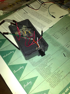
Open Arduino enclosure, showing the Arduino board nested in position and the IR decoder glued in place.


I made a hole in the enclosure using a 3/16" bit on my Dewalt drill, angling it diagonally back-and-forth to get a good wide slot (I wanted to make sure the receiver had a nice, wide field-of-view to catch IR signals). I then seated the Arduino board in the enclosure and glued the IR sensor in place with my wife's glue gun (note to self: I've stolen my wife's glue gun and owe her a new one). My gluing technique is hellishly wasteful, but I figure I'll get better with practice. One thing I love about working with glue is that it doubles as an insulator; no more wiggling my fingers in between tiny wire runs to get the electrical tape on there!

Front face of Arduino enclosure, showing the IR decoder visible through the drilled slot.
IR decoder visible through the drilled slot in the side of the enclosure.


Once the glue solidified a bit, I did a quick soldering job and was all set. I wrapped the signal and power wires around the posts in the enclosure also and threw some hot glue on there for mechanical stability (I want to make sure any jostles the wires might take are being supported by the posts and not the Arduino's female pin coupler or the IR sensor's leads).

I then fished a sticker out as a finishing touch. :)

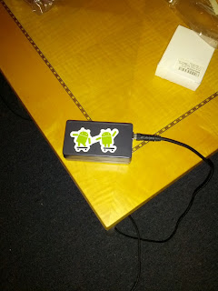
Back-face of enclosure, showing sticker depicting two Androids on skateboards.


I'm very happy with both this sensor and its range. I ran some quick tests with the full enclosure at different ranges using my old remote signal decoder program, and found it was able to sense a good distance away (about 15 feet; plenty for my needs).


What I learned

  • This IR sensor is more temperature-resistant than I'd feared it might be; I ran the soldering without any heat sinks, and no harm was done.
  • Hot glue is actually pretty safe to work with; I'd worried I would get burned, but discovered that it appears to shunt its heat pretty quickly as it transitions to a solid state. solid strands can be touched within a few seconds of being emitted from the nozzle (though blobs should be given about thirty seconds to a minute to gel cleanly; they change opacity a bit on solidification, which is convenient).
  • Hot glue is messy; spiderweb-strands everywhere, needed to go in with pliers to clean it up. Also, I'll be more careful in the future about letting the glue find its way into the seam of the enclosure itself; my enclosure no longer seats quite correctly because one blob of glue bubbled over the top and got into the joint.
Part 2 will discuss extending the software and adding status indicators.

Sunday, March 31, 2013

Ten-minute hack: Keep the snow off your windshield (just in time for spring!)

The most irritating thing about the morning weekday ritual in these northern lattitudes is scraping the show off my windshield. I'm already cold and cranky; having to do some manual labor to get the car ready to go is just icing on an anger-cake.

While I was watching TV with the family one night, a commercial came on for a windshield frost guard. I had to laugh a bit, as I said to myself "That's basically just a sheet you put over your windshield."

I decided to test that theory.

Preparation

Jersey-knit sheet. Red. Queen-size. It was on the top of the "Sheets we don't really want to put on the bed anymore" pile.

Ten-minute hack

I opened the car door and laid the sheet's short end across the top of the door frame, then shut the door.

Sheet is closed in along the top frame of the door.

Then, I stretched the sheet across, and did the same on the other side.

Sheet stretched fully across the windshield.
Add caption

It turns out my timing couldn't have been better, because we got a couple of inches that night.

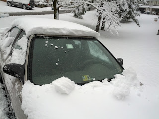
Car is covered in snow. Neither sheet nor windshield are visible.
March 25... GROUNDHOG YOU ARE ON NOTICE.
However, I just peeled the sheet back and...

Car is still mostly snow-covered, but the sheet has been removed and the windshield is completely clear.
... all set!
I shook out the sheet, threw it in my trunk, dusted off the other windows and the flat surfaces, and drove away.

Final Thoughts

Overall, I'd call it a successful experiment.

Pros

  1. It was free (amortized against the cost of a sheet destined for the rag-pile).
  2. It worked great.
  3. If the sheet ever gets too grimy, it's machine-washable.

Cons

I still don't think I'd buy a dedicated windshield cover for this job, but here are some issues I can predict happening.
  1. Jersey knit wicks water. This could be an issue if you get a rain-then-freeze weather pattern; you may end up with sheet stuck to your windshield. A waterproof material would be preferable.
  2. Since the ends of the sheet are extending into the car, they could get a little grimy and carry that grime into your car (or wick water in), which could be a problem depending on your tolerance for that sort of thing. The ones that are sold for this purpose have some stiffness to them and bungee nylon that wrap around the rear-view mirrors; if I felt like doing more than a ten-minute hack, I could probably fabricate something equivalent with bent-out coat hangers and some rope.
  3. Even after shaking the solid snow out of the sheet, the wicking action had pulled a lot of water in, and I ended up with a soggy sheet in my trunk. My trunk doesn't care about wet stuff, but if yours does, you'll want a plastic bucket to keep the sheet in.
With luck, we shouldn't have any more snow this year (HAH!). But if we do, I'm ready.

Monday, March 18, 2013

Another Year of FIRST Robotics


The FIRST Robotics regional has wrapped up in Pittsburgh, PA. I didn't really have time to participate as a mentor or volunteer this year (although I got a chance to present for my company as a sponsor, which was really nice). But I did get a chance to watch a couple of rounds. One I caught really summed up why I love FIRST.

Tem 3955 (blue, center) built a robot that could climb the pyramid rung-by-rung by repeatedly extending a two-claw gripping arm and then hooking a lower grip onto the bar below, a bit like a rock climber. The machine was a beautiful thing to watch.

But in this match, they slipped; only one hook "bit" on the highest bar of the pyramid and they were left hanging. In that position, they're worth 20 points at the end of the match, but they'd be worth 10 points more if they could get the lower chassis above the middle bar. You can hear the crowd shouting "Pull yourself up!" But if they do and the chassis bumps the middle bar, they could tumble right off and lose all 20 points (and possibly damage their robot or a teammate's robot on impact).

Scoring for the climbing pyramid. Source: http://frc-manual.usfirst.org/viewItem/3#3

Rather than risk what they already had, they decided to hold on. And in the end, it proved to be the right choice; they won the round 69-55; the twenty points they earned were instrumental to their team's victory.


This is a machine that these students built themselves in six weeks, from scratch. But it's not about the machine; it's never really about the machine. It's about the moment-by-moment decisions made by the students on and off the field. I can imagine the pressure the three-student driving team felt trying to decide how to handle the situation; at the end of the day, the moment was in their hands alone, and it's their choice that will decide whether they win or lose.

Teamwork. Quick thinking. Focus. Strategy. And also control. Knowing how to do as much as you possibly can... And no more.

And no less.

This is why I keep coming back to FIRST.