Monday, April 25, 2022

Simulating a flywheel part 2: friction and time-step updates

On a previous post, I discussed creating a simulator for a simple flywheel in the FIRST Robotics WPILib framework in Java. We last discussed the high-level framework and simulating a motor; here, we’ll go into simulating friction and how we put it all together.

Friction is deceptively complicated

On the surface, friction is extremely simple. As is taught in high school physics, it’s the force that resists motion proportional to the normal force of the surface pushing against gravity. Which is to say, it’s just -K<sub>d</sub> * m * g, for g the gravitational constant (acceleration) and m the mass of the object, and K<sub>d</sub> the dynamic friction coefficient. Since the flywheel’s axle is pushed down by gravity on its socket, the friction force becomes a counter-torque opposing spin. So, no problem. We calculate the counter-torque, subtract it from the motor’s forward torque, and update every step. Punch that in and… Oh dear.

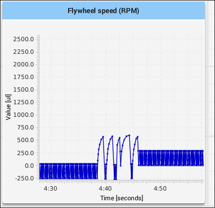
Graph of the flywheel velocity when motor on. When motor is off, the flywheel oscillates back and forth rapidly


The problem is that friction is a continuous effect: the force opposing motion applies until the object gets very close to zero velocity (relative to the surface it’s rubbing against). At that point, the molecules of the two objects “gum up” with each other and the object stops moving. But the simulator is a discrete time-step simulation: every time step, the forces acting on the flywheel are summed up, velocity is changed, and then it’s assumed the flywheel velocity stays the same until the next time step. So the velocity “wiggles” back and forth around zero without ever reaching zero and the flywheel never actually stops.

There are several solutions of various levels of complexity for handling this aspect of friction, but for our purposes we can use a fairly simple one:

  • Calculate the new angular velocity from the torques and counter-torques.
  • Check to see if the sign of the velocity has flipped. If it has, we know the velocity crossed through the zero boundary.
  • If we did cross zero, check to see if the driven torque exceeds the counter torque.
  • If it doesn’t, the motor seizes; set velocity to zero.

Code as follows:

if (Math.signum(newAngularVelocityRps) != Math.signum(flywheelAngularVelocityRps)
    && flywheelAngularVelocityRps != 0
    && newAngularVelocityRps != 0) {
    // Crossed zero boundary; if torque is too low to overcome friction, motor seizes
    if (Math.abs(advantagedTorque) < Math.abs(counterTorque)) {
        newAngularVelocityRps = 0;
	}
}

One other aspect of friction to account for: Static friction generally exceeds dynamic friction, and applies if the flywheel is starting from zero velocity. We account for that by selecting the right friction coefficient based on whether the motor is moving and comparing the torque to the counter-torque from the friction; if driven torque does not exceed counter-torque, the motor doesn’t start.

var frictionCoefficient = m_motorSpeedRpm == 0 ?
          m_flywheelStaticFrictionConstant.getDouble(1.0) :
          m_flywheelDynamicFrictionConstant.getDouble(1.0);
// ...
var totalTorque = advantagedTorque - counterTorque;
if (m_motorSpeedRpm == 0 && Math.abs(advantagedTorque) < Math.abs(counterTorque)) {
    // stalled motor does not overcome static friction
    totalTorque = 0;
}

Putting it all together

Having accounted for friction, we now only need to take the total torques computed and apply them to how the velocity and encoder count changes over time.

To start, the total torque changes the angular velocity. Similar to the famous F = ma equation, torque = moment of inertia * angular acceleration. So we divide our torque by the moment of inertia to get an acceleration, and add it (times the time delta step) to the velocity:

var angularAccelerationRadsPerSec = totalTorque / m_flywheelMomentOfInertiaKgMSquared.getDouble(1.0);
var flywheelAngularVelocityRps = Units.rotationsPerMinuteToRadiansPerSecond(m_motorSpeedRpm) / gearRatio;

// Update angular velocity, parceling the change by the delta-T
var newAngularVelocityRps = flywheelAngularVelocityRps + angularAccelerationRadsPerSec * TIMESTEP_SECS;

Then, we just need to update the velocity and position for the encoder, and update the RPM graph:

m_motorSpeedRpm = Units.radiansPerSecondToRotationsPerMinute(newAngularVelocityRps * gearRatio);

// multiply by timestep and ratio of rotations to radians to get new flywheel position
var flywheelSpeedRotationsPerSec = newAngularVelocityRps / (2 * Math.PI);
var flywheelDelta = flywheelSpeedRotationsPerSec * TIMESTEP_SECS;

// encoder values are relative to flywheel, not motor
m_encoder.setDistance(m_encoder.getDistance() + flywheelDelta);
m_encoder.setRate(newAngularVelocityRps);

m_flywheelSpeedRpm.setDouble(flywheelSpeedRotationsPerSec * 60);

And we’re done! We have a self-updating flywheel simulation that we can experiment with.
Monday, April 18, 2022

Simulating a Flywheel part 1: overview and simulating a motor

Well, the off-season of FIRST Robotics is upon us. A time when young people’s minds turn away from robots and towards other things. Like simulating robots!

To give the team something to play with on the software side, I’m putting together a couple of simulators of robot subsystems to experiment with. The first one is a simple flywheel connected to one motor and encoder.

The interface for the simulator in Shuffleboard
Interface for the simulator, showing the graph of flywheel RPM over time

I’m going to break the discussion of how I did this into two parts. Here, I’ll go over the top-level architecture of the program and how it tries to simulate, and talk about the equations to simulate a DC electric motor. In a follow-up post, I’ll go over the physics of friction simulation.

Full disclosure: I’m a rank amateur at this, putting together half-remembered high school physics, a barely-used robotics minor, and some hazy memories of graphs from my first years playing FIRST Robotics. Definitely room for improvement, and I welcome feedback on this.

You can get the simulator from the GitHub repsitory.

Overview

Program structure

The program is a simple TimedRobot operating at the default frequency of 50 times a second. It includes one automatically-running Flywheel subsystem that lets a motor be turned on and off (at max power or 0 power), which is controlled by a single joystick button.

In addition to Flywheel, a SimulatedFlywheel class is constructed if the robot is operating in simulation mode. This class takes in the motor from the Flywheel and a simulation wrapper around the encoder, allowing us to explicitly set the encoder’s position and velocity values.

The simulation

At a high level of abstraction, the torque on a motor-driven flywheel at any moment is simple:

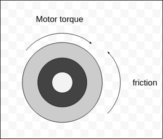
Total torque = motor torque - friction torque

Spinning flywheel, with forward force and opposed force
Opposed forces acting on a spinning flywheel

Once we have calculated this torque, we can update the flywheel’s angular velocity by adding total torque / moment of inertia to the flywheel’s previous velocity. Then we update the flywheel’s position as well (accounting, in both cases, for the step of time over which this change is occurring, in our case 20ms between updates).

That’s the high-level approach; let’s drill down on the details.

Simulating motors

A DC motor is a relatively simple system, but it has a bit of complexity making simulating one interesting.

The basic principle by which a DC motor operates is that half of the motor uses electromagnets, while the other half uses permanent magnets. Varying the current through the motor’s electromagnets creates moving magnetic fields that the permanent magnets then “chase,” turning electricity into motion. The highest torque such a motor can give is when it’s “stalled” (i.e. not moving) and the voltage across it is maximized. At this configuration, the motor is pushing with its “stall torque” (note: It’s generally a bad idea to leave a motor stalled like this; many DC motors aren’t designed to run current through with no motion, and doing so for long periods of time can heat up and damage components).

So the total torque a motor can give is equal to some constant times the current through the motor:

motor torque = I * k_M

Where I is current through the motor and kM is a torque constant. Note: equations for motor behavior are mostly sourced from here. We can quickly calculate kM as just the stall torque divided by the current, but for the purposes of the simulation i find it easier to just consider a relationship between stall torque and voltage by subsituting current through V = IR, then considering the motor with 12 volts across it and finding the value of a constant q which is resistance divided by KM:

q = 12 / motor stall torque

What’s interesting about electric motors is that when I say “some loops of wire acting as electromagnets near some permanent magnets,” I’m also describing a type of generator. And indeed, a spinning electric motor tries to induce a current in the direction opposite the spin! This opposing force, known as “back-EMF” (EMF: electromotive force), creates a counter-voltage to the voltage across the motor, resulting in a drop in current through the circuit. The physics of why this happens can be a little confusing, but there’s (I think) an elegant way to remember it: the fact that motors have back-EMF sort of falls naturally out of conservation of energy once we remember that motors with a voltage across them don’t spin up to infinite speed. Since a motor spinning at top speed only needs a little bit of energy to overcome resistance and maintain that speed, and since energy lost across a component of a circuit is the power (P=IV), we know that when the motor is spinning near top speed, P across the motor must be small to keep it spinning, so current and/or voltage diminished.

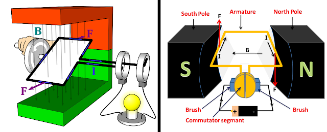
Diagram of an electric generator and an electric motor
An electric motor and electric generator differ mostly in where the energy comes from. (Images sourced from Wikimedia)

The back-EMF on the motor is proportional to the motor’s rotational speed and some back-EMF constant ke.

Diagram of an electric generator and an electric motor

A motor allowed to spin up to full speed under no load and with maximum voltage across it will spin at a “free speed” which varies from motor to motor. At free speed, the back-EMF is approximately equal to the forward voltage, so we can set the voltage and speed in the above equation and re-arrange to solve for the back-EMF constant:

back-EMF constant = voltage / free speed

We’re closing in on simulating the torque. The remaining ingredient is the full torque equation.

To approach the final torque equation, we start by considering that the total voltage across the motor is the V=IR relationship through the motor plus the back-EMF value.

voltage = (current * resistance) + (motor speed * back-EMF constant

Substituting in the relationship between torque and current, we find

voltage = (motor torque * resistance / motor torque constant) + (motor speed * back-EMF constant)

Now we have voltage, motor speed, and motor torque related. Doing the algebra to make torque the dependent variable and substituting our constant for resistance divided by kM, we get:

motor torque = motor voltage - motor speed * back-EMF constant / q

That gives us the motor torque in almost all circumstances, save one: what happens when the voltage is set to zero?

Brake or coast?

It’s a subtle bit of architecture, but an important one: as we’ve established, a motor acts like a generator. So what happens when the motor should be applying no power?

Motor controllers used in the FIRST Robotics competition are generally configurable to “brake” or “coast” mode. In “brake” mode, the controller short-circuits the motor to itself, allowing the back-EMF to try and drive the motor in reverse. This will resist motion in the motor and drag it to a halt much quicker. The mathematics of this is, honestly, something I don’t know.

“Coast” mode is much easier to model: in “coast” mode, the controller opens the circuit. With no ability for electricity to flow from one end of the motor to the other, the motor basically contributes no torque and the flywheel will spin down normally. So we special-case the zero-voltage condition to eliminate the motor torque, simulating “coast mode.”

Next steps

This gives us half the flywheel simulation. Next time, we’ll talk about the friction counter-torque (and how annoying friction subtleties are!) and tie it all together with the acceleration and velocity-update logic.


Monday, April 11, 2022

Piping Linux audio to a file

I recently had to pipe some audio from my browser to a file. This may not be the most elegant way, but I found it works.

Using SimpleScreenRecorder

For capturing audio and video, I use SimpleScreenRecoder. It’s a pretty no-frills recording program that is intended for (among other things) streaming content from a machine. While it supports both audio and video, I only care about the audio portion for this project.

To minimize bandwidth wasted recordin video, I set “Record a fixed rectangle” and set a 2x2 rectangle at 0,0. I then enabled “Record audio” with the PulseAudio backend and a Source of Monitor of sof-hda-dsp Speaker + Headphones. That output to my computer’s main speakers.

Image of the SimpleScreenRecorder UI, showing the configuration

On the next screen, I set up an Output profile declaring the destination, use of MP4 as the container, an H.264 video codec with constant rate factor of 23, superfast preset, and “Allow frame skipping”, and an Audio codec of MP3, Bit-rate 128 kbit/s). 

Once set up, I could just start recording.

Monday, April 4, 2022

Resetting my monitor in Linux

Recently, I had an Ubuntu laptop I use regularly develop a weird quirk: sometimes when I plugged it into USB-C, neither the monitor nor power would connect. I discovered I could fix this by simply running lspci on the laptop, which somehow forced both to come back.

As this made no sense, I dug down a bit more. I can’t say I found an answer, but I did find some more things worth questioning.

PCI devices

On my laptop, devices are exposed at /sys/bus/pci/devices. Searching around a bit, I found that device /sys/bus/cpi/devices/0000:3b:00.0 was reporting itself as USB controller: Intel Corporation JHL6540 Thunderbolt 3 USB Controller (C step) [Alpine Ridge 4C 2016] (rev 02). Navigating into that subdirectory, I found I could sudo -s, then echo 1 > reset, which fixed the system in apparently the same way as running lspci.

What the hell?

At this point, I don’t really know. Sometimes the Linux architecture just puzzles me. I don’t know that lspci is running a reset on devices, but perhaps when it tries to poll details on the device, the act of polling itself trips a fault in the driver (becuase the driver realizes it can’t communicate with the device) and forces a reset to heal itself? I haven’t found any code confirming or falsifying this hypothesis; it’s still an open question for me.

On not giving up

Owning a Linux machine is like this. When things go wrong, the only person who’s responsible for fixing it is the owner. This is, ultimately, true of all self-owned computers, of course.

When I was younger, the ecosystem of Linux users was too hard to find to make this task easy; certainly not as easy as it was for Windows ownership, when everyone on the block had one of those machines. But the nice thing about living in the Internet era is Linux use bloomed, and at the same time users can find each other much more easily. I learned about the existence of the PCI list poking around on various sites.

There’s much more to learn, but it’s nice that resources are far easier to find now.